Old Designs for Game-Playing Robot
Design 1 - Python Script
My first design was very straightforward.
- Take screenshots of Valorant
- Look for enemies in the screenshot
- Command the 3D printer over USB to aim at the enemy
- The 3D printer executes my command
- Do this 60 times per second
Easy, right?
1.1 Looking for enemies
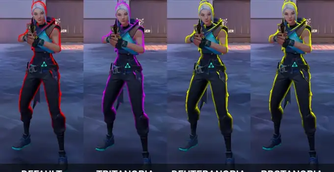
Enemies in Valorant have a distinct outline to make them stick out from the environment. You can use simple color filtering for those colors to figure out where they are located on the screen.
screenshot = ImageGrab.grab()
screenshot_array = np.array(screenshot)

lower_red_bound = np.array([0, 0, 140])
upper_red_bound = np.array([100, 100, 255])

# Results in bitmap of pixels that are colored red
red_pixels = cv2.inRange(screenshot_array, lower_red_bound, upper_red_bound)
Assuming there is only one enemy on screen, the average
(x,y) coordinate of all red pixels on screen gave me an
approximation of the enemie’s “center of mass” and thus where I want to
aim.
1.2 Controlling the 3D printer
When you want to print a 3D model, you need to “slice” the model into a “GCode file” which you then execute on the 3D printer. GCode files are like Python turtle programs — step-by-step instructions for the 3D printer.
M104 S185 # Set temperature of nozzle
G0 1 0    # Move nozzle 1u up
G0 0 1    # Move nozzle 1u right
G0 0 -1   # Move nozzle 1u down
G0 -1 0   # Move nozzle 1u left
Typically, you would load the GCode file onto an SD card and insert it into the 3D printer, but you can actually send GCode instructions over USB, one at a time.
import serial

port = "/dev/ttyUSB0"
ser = serial.Serial(port, 9600, timeout=1)

ser.write(b'G0 10 10')

ser.close()
I can use this to control the 3D printer in real time.
1.3 Putting It All Together
Now we can do all of this at 60Hz:
- Find the position of the enemy relative to the crosshair.
- I take a screenshot of the game.
- I use color filtering on the screenshot to find the red outlines of enemies.
- Create bounding rectangles for the pixels to find individual enemies.
- Find the positions of the enemies relative to the crosshair.
- Choose the enemy closest to the crosshair.
- Calculate how the 3D printer should move in the.
- The 3D printer receives the command and executes it.
- The 3D printer firmware handles this by itself.
… but this didn’t work at all. The movement was either choppy or delayed no matter how I tuned it. I realized all my problems were caused by the firmware of the 3D printer — the program that’s recieving the GCode commands. The way it handles commands did not suite my project.
Uninterruptable Command Queue
When you send commands to the 3D printer while it is currently in the middle of executing a command, it will queue the new command. Once it finishes the command it’s executing, it will dequeue to get its next instruction. It will not cancel the currently executing command nor is there a way to do that (to my knowledge).
Suppose you send commands that take Δt to finish once every Δt seconds. This should theoretically work fine because as soon as the current command finishes, it will receive a new command with virtually no downtime or latency. But if your command durations or command frequency are desynchronized, then you will have a terrible issue. Either:
- The commands take too long to execute, causing the command queue to fill up. Whenever you send a command, it will have to wait until it is reached in the queue. This causes a great lag between when you send the command and when it gets executed.
- The commands take too short to execute. When the 3D printer has nothing to execute, it won’t move. These momentary stops cause the 3D printer to have horrible stutters.
Acceleration Curve
The 3D printer will always decelerate to 0 after every command. This means that between every command, it will momentarily stop. Since I was trying to run multiple commands each second, this made it jittery. To solve this, I could run less commands per second but that lower my robot’s reaction speed. I couldn’t find a good balance.
Design 2 - Hand-Written 3D-Printer Firmware
If replace the 3D printer’s firmware with something else, then I can make this robot work better. I decided to write my own.
- Take screenshots of Valorant
- Look for enemies in the screenshot
Command the 3D printer over USB using GCode to aim at the enemy- Command the 3D printer over USB using my own protocol to aim at the enemy
The 3D printer executes my command- My custom firmware executes my command
- Do this 60 times per second
Easy, right?
2.1 Writing New Firmware for 3D Printers
My 3D printer is a Monoprice Maker Select V2 which has a Melzi 2 control board.
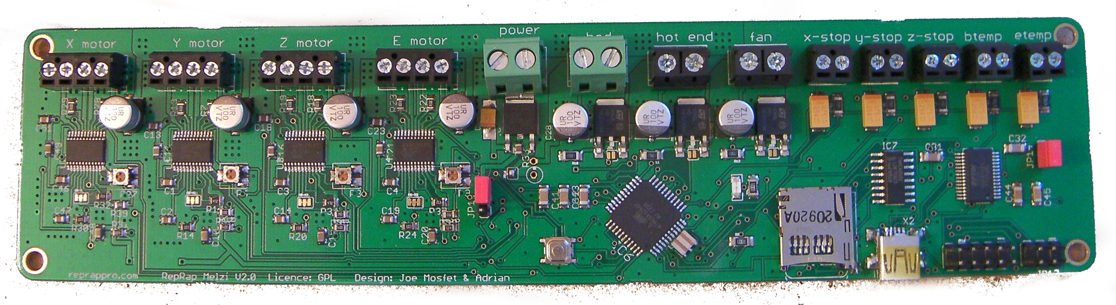
Despite how it looks, this board is literally just an Arduino. It has an ATMEGA1284P processor which is a Sanguino microcontroller. Sanguinos are high-performance chips that are compatible with Arduino software.
Initially, there’s no way to overwrite the default 3D printer firmware. I had to follow this guide to install a bootloader, which lets me upload C++ code to the Melzi using the Arduino IDE just like any other Arduino.
For this blog post, I’m using pseudocode to make thing simpler. If you want to learn about writing firmware for 3D printers in detail, read this post.
The code comes in two parts — getting the data from USB, and then moving the motors according to the given state.
int xDisplacement, yDisplacement;

while true {
  xDisplacement, yDisplacement = getDataFromUSB();
  moveMotors();
}
2.2 New Communication Format
Since we’re getting rid of the 3D printer firmware, we can drop g-code entirely. I switched to a new format that’s a lot easier and faster to use.
Simple: 3 bytes. The first two are 1-byte signed integers which
denotes the displacement the enemy is from the crosshair. The third bit
is 0, and is used for alignment. The first two bytes can’t
be 0 so we can’t get them confused.
bool correctingError = false;
void updateError() {
if (correctingError && Serial.available()) {
byte data = Serial.read();
if (data == END_BYTE) {
correctingError = false;
}
}
if (Serial.available() >= 3) {
byte data[3];
Serial.readBytes(data, 3);
if (data[2] == END_BYTE) {
updateVars(data[0] - 128, data[1] - 128);
} else {
correctingError = true;
}
}
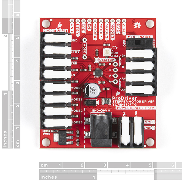
}2.3 Moving Servos
We can control each servo using a set of digital pins:
- Enable - Lock/unlock the motor
- Direction - Chooses the direction the motor will move
(
0=clockwise,1=counterclockwise) - Step - Toggling this moves the motor 1 “step”
- Step mode - An n-bit signal that decides how big a step is
For example, here’s some pseudocode that will move the motor as fast as possible:
CW, CCW = 0, 1
digitalOutput(DIRECTION_PIN, CCW)
stepState = False
for _ in [0..numSteps]:
  digitalOutput(STEP_PIN, stepState)
  stepState = ~stepState # Invert state
The faster you can toggle the state of STEP_PIN, the
faster the stepper motor goes. Additionally, this means our program must
be in the form of a very efficient loop. We must toggle the state
regularly or else the stepper motor will jitter.
Irrelevant rant
There’s one thing I want to note about development on a Melzi board that frustrates me dearly. Stepper motors move in units called “steps” which is dependent on the specific design of the given motor, and is typically 30 degrees. In order to make the motor move a step, you need to alternate the STEP_PIN. If I want to make the motor move 5 steps, I alternate the STEP_PIN 5 times. Stepper motors can also move in half, quarter, eigth and potentially up to 256th of a step depending on the motor. Larger steps make it move faster, and smaller steps allow more precision.
Whether the stepper driver will make the motor move in full, half,
quater, etc steps depends on what mode it is in. That can be decided by
using the mode pins. The melzi pinout doesn’t have any pins to choose
the mode because the drivers are hard wired to stay on the 1/16th-step
mode. 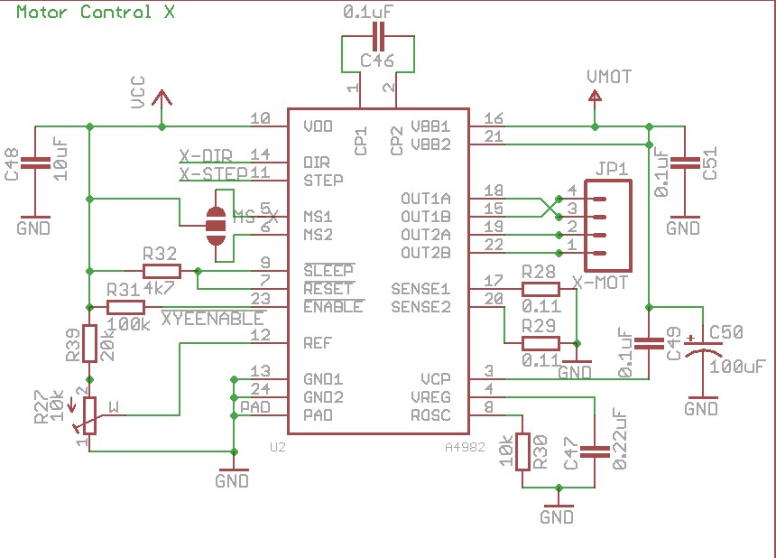
2.4 Proportional Integral Derivative Control
We can state this problem in terms of error correction. The number of pixels the robot is away from the enemy is the error, and our goal is to make this error zero. When the error is zero, it means our crosshair is right on top of the enemy. PID is a very classic algorithm used in robotics and I used it all the time in my high school’s FIRST robotics club, but I didn’t feel this problem needed a full-blown PID algorithm. The output of PID tells me what speed I need to set the motor to quickly and smoothly move the motor to a position, but I didn’t have such direct control over the speed. As shown in the previous section, all I could do is move it one step at a time.
I had to take an alternative approach. “Inverse P” is not a real control system, but it’s the most natural solution to this problem under the given restrictions.
step = 0
while True:
    error = get_error()
    period = c * 1. / error
    if step % period == 0:
      moveMotorOneStep()
    step += 1
The higher the error, the higher the frequency the motor would be moved one step, and thus the faster the motor will move.
2.5 Putting it all together
- Python code running on computer
- Take screenshot of game and find location of enemy exactly the same as in part 1
- Send the displacement between the crosshair and enemy over USB to the 3D printer
- New firmware running on 3D printer
- Recieve the data from USB
- Calculate the new speed at which it should move the motors
- Move the motors
This worked! But not that well…