My 3D Printer Plays Video Games Better Than You
My friends always say I'm trash at Valorant and I play worse than a bot, so I made a robot that plays better than them.
I wanted the robot to literally use a keyboard, mouse, and monitor to play the game so it plays exactly like a human --- no memory exploits whatsoever like in most game hacks.
I had no money so I couldn't buy high-quality servos, power supplies, and other materials --- but I did have a 3D printer! If I attach my mouse to the printer nozzle, I can move the mouse by moving the nozzle.
@butt_kisser 3D printer glowup #3dprinting #techtok #coding #arduino #makersoftiktok #programming #computerscience #computersciencemajor #gaming ♬ som original - 𒉭
This project went through quite a few iterations. My first attempt at this project was fundamentally flawed and couldn't shoot a target standing still. My second attempt could beat most of my friends... except for one. He was a top .5% player and the person I wanted to beat the most.
It took the culmination of almost all the skills I had to be able to make something that could beat him. I was really big into robotics during high school, and I spent the latter two years focusing on making our robot's PID control systems as performant as possible. In my freshman year of college, I did in an internship at an aerospace company where I worked on developing an FPGA-based coprocessor for physics simulators used to test plasma propulsion engines. This final design was the unification of these two ideas. That jerk now brags that it took rocket science to beat him.
Design 1 — Python OpenCV
My first design was very straightforward.
- Take screenshots of Valorant
- Find enemies in the screenshot
- Command the 3D printer over USB to aim at the enemy
- Repeat at 60 Hz
Easy, right?
1.1 Finding enemies
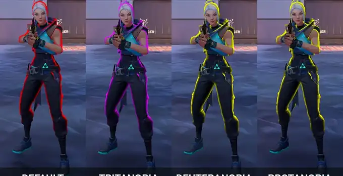
Enemies in Valorant have a distinct red outline. Color filtering is enough to localize them.
screenshot = ImageGrab.grab()
screenshot_array = np.array(screenshot)

lower_red_bound = np.array([0, 0, 140])
upper_red_bound = np.array([100, 100, 255])

red_pixels = cv2.inRange(screenshot_array, lower_red_bound, upper_red_bound)
Assuming there is only one enemy on screen, the average (x,y) coordinate of all red pixels on screen gave me an approximation of the enemie's "center of mass" and thus where I want to aim.
1.2 Controlling the printer
3D printers normally run sliced G-code files: Python-turtle-style step commands for the nozzle.
M104 S185 ; set nozzle temperature
G0 1 0    ; move 1 unit up
G0 0 1    ; move 1 unit right
G0 0 -1   ; move 1 unit down
G0 -1 0   ; move 1 unit left
Typically, you would load the GCode file onto an SD card and insert it into the 3D printer. You can also stream G-code over USB one line at a time:
import serial

ser = serial.Serial("/dev/ttyUSB0", 9600, timeout=1)
ser.write(b"G0 10 10")
ser.close()
I can use this to control the 3D printer in real time.
1.3 Putting it together
Each frame:
- Screenshot the game, filter for red outlines, pick the enemy closest to the crosshair
- Compute how far the nozzle should move
- Send a G-code move command
...but this didn't work at all. Movement was either laggy or stuttery no matter how I tuned it. I learned the cause was the printer's firmware.
- Uninterruptible command queue:
If the printer is mid-command and you send another, the new one waits in a queue. There is no cancel. If command duration and send rate drift out of sync:
- Commands pile up and ther will be large latency between sending a command and getting executed.
- If there is a gap between commands, the head stops between moves which causes stutter.
- Acceleration between moves: Stock firmware decelerates to zero after every segment. At 60 commands per second that feels like constant jitter. Fewer commands helped smoothness but hurt reaction time. I could not find a workable middle ground.
Design 2 — Custom Firmware on the Melzi
If replace the 3D printer's firmware with something else, then I can make this robot work better. I decided to write my own.
- Take screenshots of Valorant
- Look for enemies in the screenshot
Command the 3D printer over USB using GCode to aim at the enemy- Command the 3D printer over USB using my own protocol to aim at the enemy
The 3D printer executes my command- My custom firmware executes my command
- Do this 60 times per second
Easy, right?
2.1 The board
My 3D printer is a Monoprice Maker Select V2 which has a Melzi 2 control board.
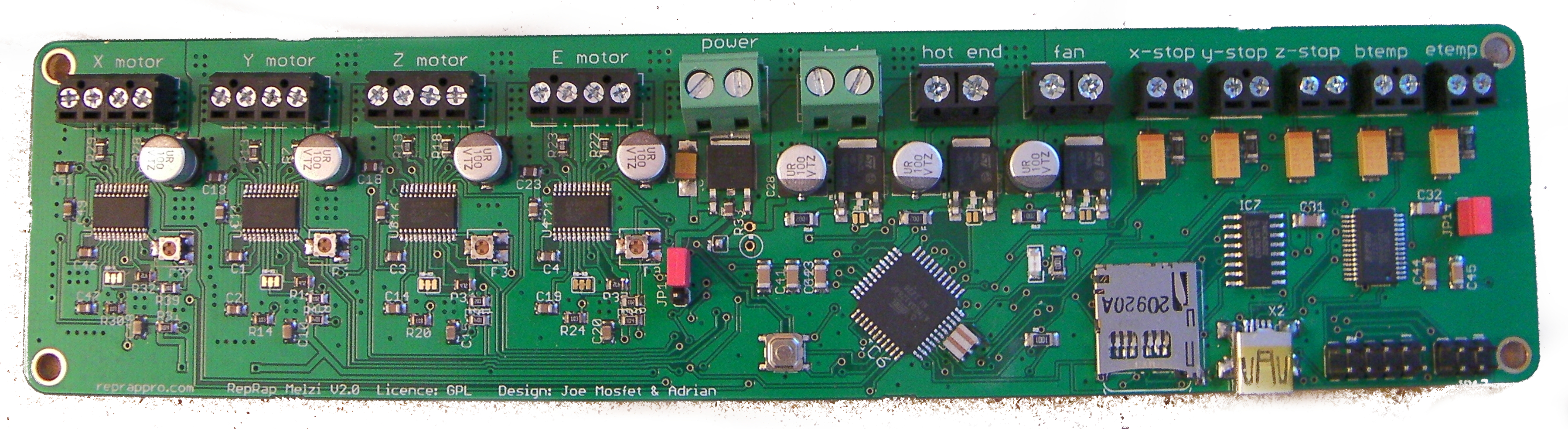
Despite how it looks, this board is literally just an Arduino. It has an ATMEGA1284P processor which is a Sanguino microcontroller. Sanguinos are high-performance chips that are compatible with Arduino software.
I flashed a bootloader using this guide so I could upload firmware from the Arduino IDE.
The code comes in two parts --- getting the data from USB, and then moving the motors according to the given state.
int xDisplacement, yDisplacement;

while (true) {
  xDisplacement, yDisplacement = getDataFromUSB();
  moveMotors();
}
2.2 USB protocol
Three bytes per update: signed X offset, signed Y offset, and a fixed 0 terminator so the stream can resync after corruption.
bool correctingError = false;

void updateError() {
  if (correctingError && Serial.available()) {
    byte data = Serial.read();
    if (data == END_BYTE) {
      correctingError = false;
    }
  }
  if (Serial.available() >= 3) {
    byte data[3];
    Serial.readBytes(data, 3);
    if (data[2] == END_BYTE) {
      updateVars(data[0] - 128, data[1] - 128);
    } else {
      correctingError = true;
    }
  }
}
2.3 Stepper control
We can control each servo using a set of digital pins:
- Enable - Lock/unlock the motor
- Direction - Chooses the direction the motor will move (
0=clockwise,1=counterclockwise) - Step - Toggling this moves the motor 1 "step"
- Step mode - An n-bit signal that decides how big a step is
For example, here's some pseudocode that will move the motor as fast as possible:
CW, CCW = 0, 1
digitalOutput(DIRECTION_PIN, CCW)
stepState = False
for _ in [0..numSteps]:
  digitalOutput(STEP_PIN, stepState)
  stepState = ~stepState # Invert state
The faster you can toggle the state of STEP_PIN, the faster the stepper motor
goes. This means our program must fast. We need to toggle the state frequently or else the stepper motor
will jitter.
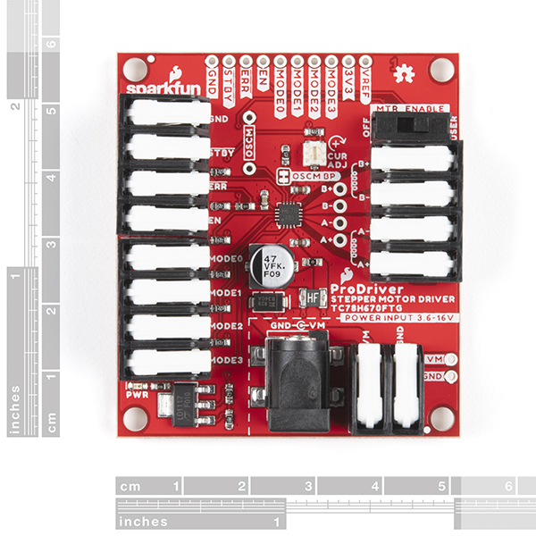
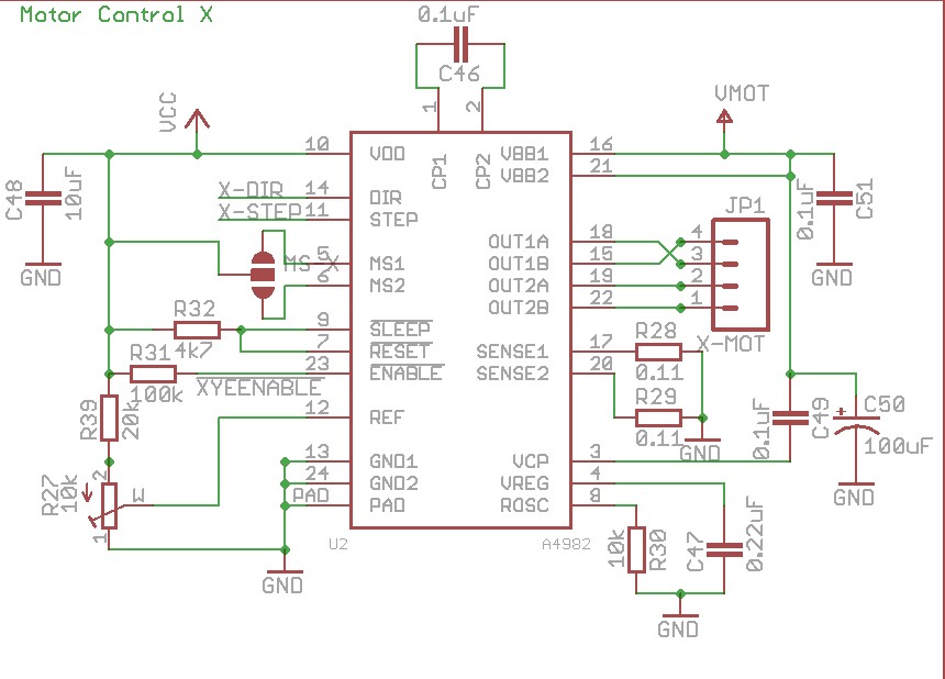
Stepper motors move in discrete steps (often 1.8° per full step). Finer microstepping trades speed for precision. The Melzi hard-wires its drivers to 1/16 microstepping with no runtime mode pins, so I could not switch to full steps for large flicks and fine steps for tracking.
2.4 “Inverse P” instead of PID
I wanted classic PID from FIRST robotics, but I did not have direct velocity control — only “take one more step now or not.”
step = 0
while True:
    error = get_error()
    period = c / error
    if step % period == 0:
        move_motor_one_step()
    step += 1
The higher the error, the higher the frequency the motor would be moved one step,
2.5 Putting it all together
- Python code running on computer
- Take screenshot of game and find location of enemy exactly the same as in part 1
- Send the displacement between the crosshair and enemy over USB to the 3D printer
- New firmware running on 3D printer
- Recieve the data from USB
- Calculate the new speed at which it should move the motors
- Move the motors
This worked! But it just wasn't fast enough.
Design 3 — VGA and the FPGA
Design 3 kept the Melzi firmware and printer mechanics from design 2. What changed was perception — tap the video cable, detect red in hardware, and close the loop before the frame finishes drawing.
3.1 High level overview
- Enemies in Valorant are outlined in red.
- Find blobs of red in the video stream.
- Move the mouse so the crosshair sits on the blob centroid.
- Click when aligned.
3.2 Low level overview
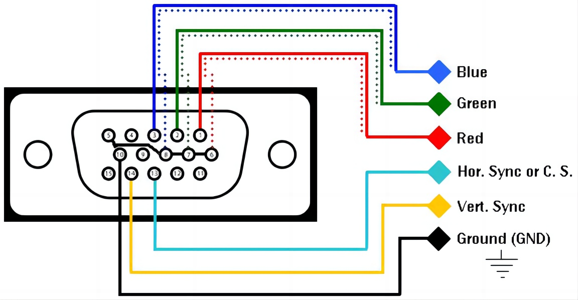
- Take your VGA video cable and cut it open.
- Compare R, G, and B voltages to emit a single “is this pixel red?” bit per clock.
- An FPGA scans the bitstream and tracks a running mean of red-pixel positions each frame.
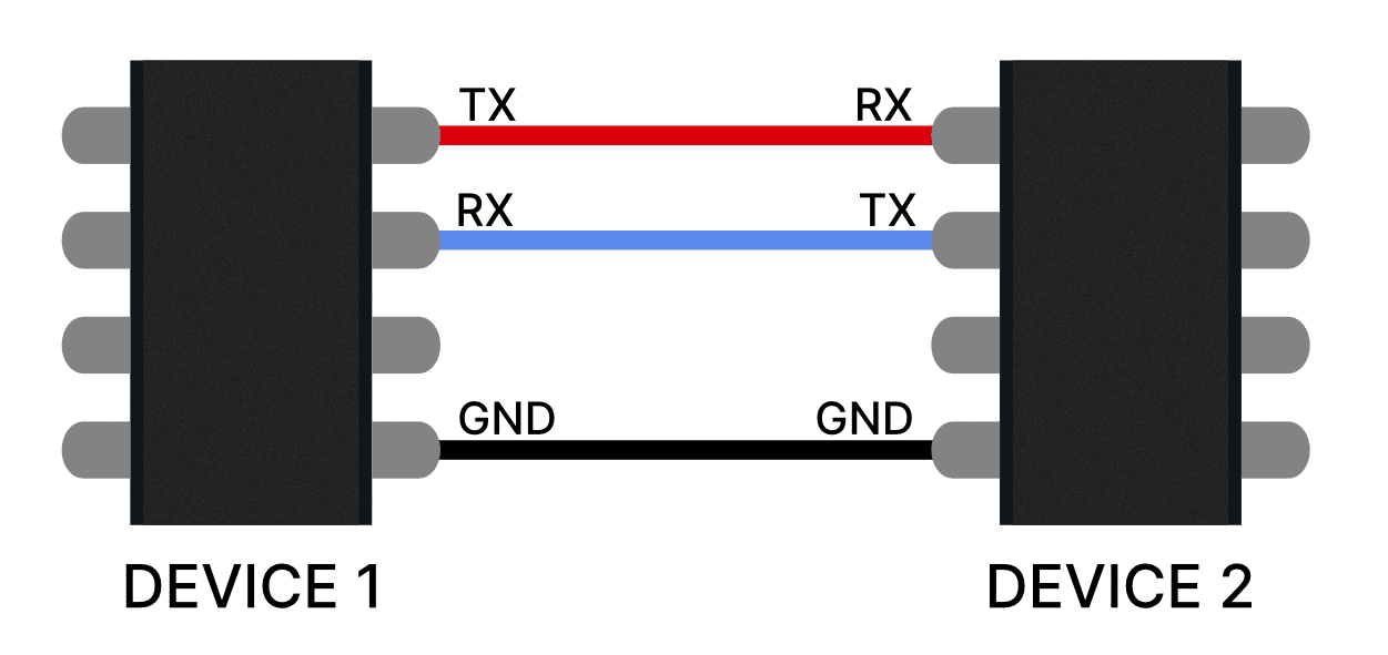
- The Arduino Vidor’s ARM core reads that mean and forwards it over UART to the printer controller.
- The 3D printer moves the computer mouse to the correct position.
- A servo taps the mouse button when the error vector is near zero.
3.3 VGA: why bother?
HDMI and DisplayPort need dedicated decode chip. VGA uses a very primitive video transmission format and is effectively transmitted as "plain text". This makes it a lot easier for me to work.
In VGA, three wires carry R/G/B voltages (0–0.7 V per channel), and horizontal/vertical sync tell you when each row and frame begin.
Each pixel is “on the wire” for one dot clock. That means you can process video as it arrives, before the frame finishes drawing on the monitor — as long as your logic keeps up with the dot rate.
3.4 Analog red detection
We need to convert the analog VGA signal into binary values.
I could convert each RGB value into 3 8-bit digital signals, but it's hard for my FPGA to take in that many inputs. Instead, I implemented all the "look for red pixels" logic into this analog circuit part. Now I only have to communicate one bit - 1 for red and 0 for not red.
I used a voltage comparator to compare the voltage levels of the red channel against the green and blue channels, essentially checking if the red signal is significantly higher than the others, indicating a "red" signal.
If red is significantly stronger than green and blue? Output 1 for enemy-colored pixels, 0 otherwise.
3.5 FPGA centroid tracking
An FPGA is a special circuit that can be transformed into other circuits. It's literally like magic. You can write code in a "hardware description language" to describe a digital circuit, upload the code to the FPGA, and it will pretend to be that physical circuit. It's typically used for developing circuits so you don't have to fabricate a new circuit board or chip every time you want to test something.
I used an Arduino MKR Vidor 4000 because I already owned one. Devices like the Arduino Vidor are cool because they have an FPGA and a normal CPU on one board. Just like how your CPU and GPU work together, you can make the CPU and FPGA work together. They can communicate with each other to accomplish tasks.
I made a circuit that calculates the "mean" position of all the red pixels. This is an approximation of the center of mass of enemies. The underlying algorithm looks something like this:
x = y = 0
sum_x = sum_y = count = 0

while True:
    is_red, h_sync, v_sync = read_pins()

    if v_sync:
        emit(sum_x / max(count, 1), sum_y / max(count, 1))
        x = y = 0
        sum_x = sum_y = count = 0
    elif h_sync:
        x = 0
        y += 1
    else:
        if is_red:
            sum_x += x
            sum_y += y
            count += 1
        x += 1
In hardware this is just counters and adders running at pixel rate.
The board controlling the 3D printer is also Arduino-based. I connected them using two wires so they could communicate over UART. Arduino has out-of-the-box support for UART so this was trivial to do.
3.6 Back to the printer
The Melzi still runs the firmware from design 2: binary offsets over serial, tight stepper loops, inverse-P stepping from pixel error. Design 3 only changed where the coordinates come from.
When horizontal and vertical error is small enough, a servo physically clicks the left mouse button.